|
|
|
Outboard DDD Ok so we have our system overview, some requirements and were ready to get down to the nuts and bolts. In the detailed design document we will specify our components, interfaces and production format. We need then to revisit our requirement and start tying down how we will meet them. To aid this section Iíve numbered the requirements as we \can work on each requirement in turn;
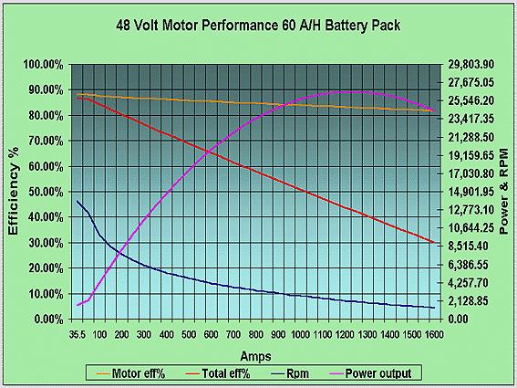
1. Power. Weíre all used to seeing motors rated in horse power but in the world of electric drives its more normal to rate drives in kilowatts or kW. 1 horsepower [international] = 0.745 699 87 kilowatt. So we need an electric drive that can produce a minimum of 7.5 kW (OK I rounded up). 2. Speed The beauty of electric drives is there all quite happy to sit a 0 rpm as opposed to the original dyno burner that rarely falls below 1000 rpm. 4000 rpm should be attainable by most forms of electric drive but weíll list a few and keep our options open at this stage. So we browse teh net and our catalogues and come up with; Lynch motor (our original stabb) at 48 Volts outputs around 8.4 kW but only runs to 3000 rpm, still at 11 Kg very good energy density so could be used if we could concession the speed requirement. ADC 140-07-4001 5.5Ē series motor. This type of motor produces very high low speed power and will run to our 4000 rpm requirement however its power output is inversely proportional to its speed so it would be unlikely to be able to actually reach the desired speed we require. (Note a boat propellor like a fan has a torque requirement that is proportional to the speed and in fact speed squared). AC 4 pole squirrel cage motor could be used but again will only run to 3000 rpm. The LAAA4002 DC series wound fan assisted motor from Gravitron will meet the speed and power requirement with additional speed capability. The reservation being that it would be easy to over speed this motor although the drive load characteristic will help us here. At 20 kg the motor is reasonably light for power but this does only leave 10 kg for our drive leg.
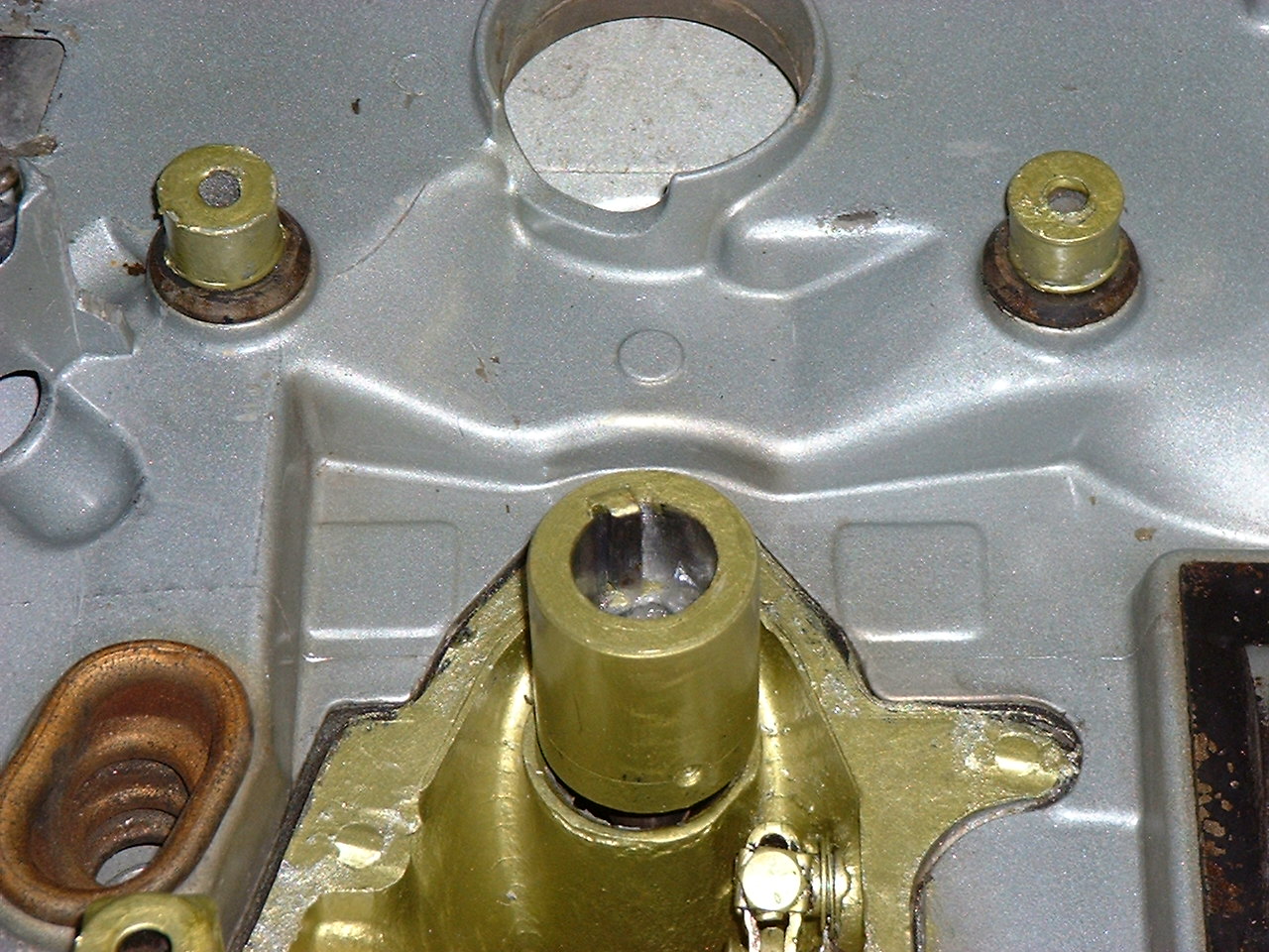
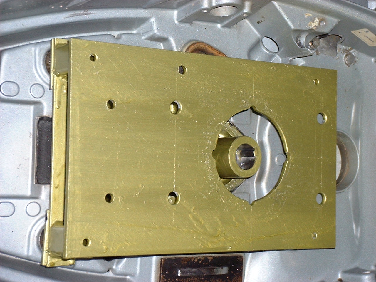
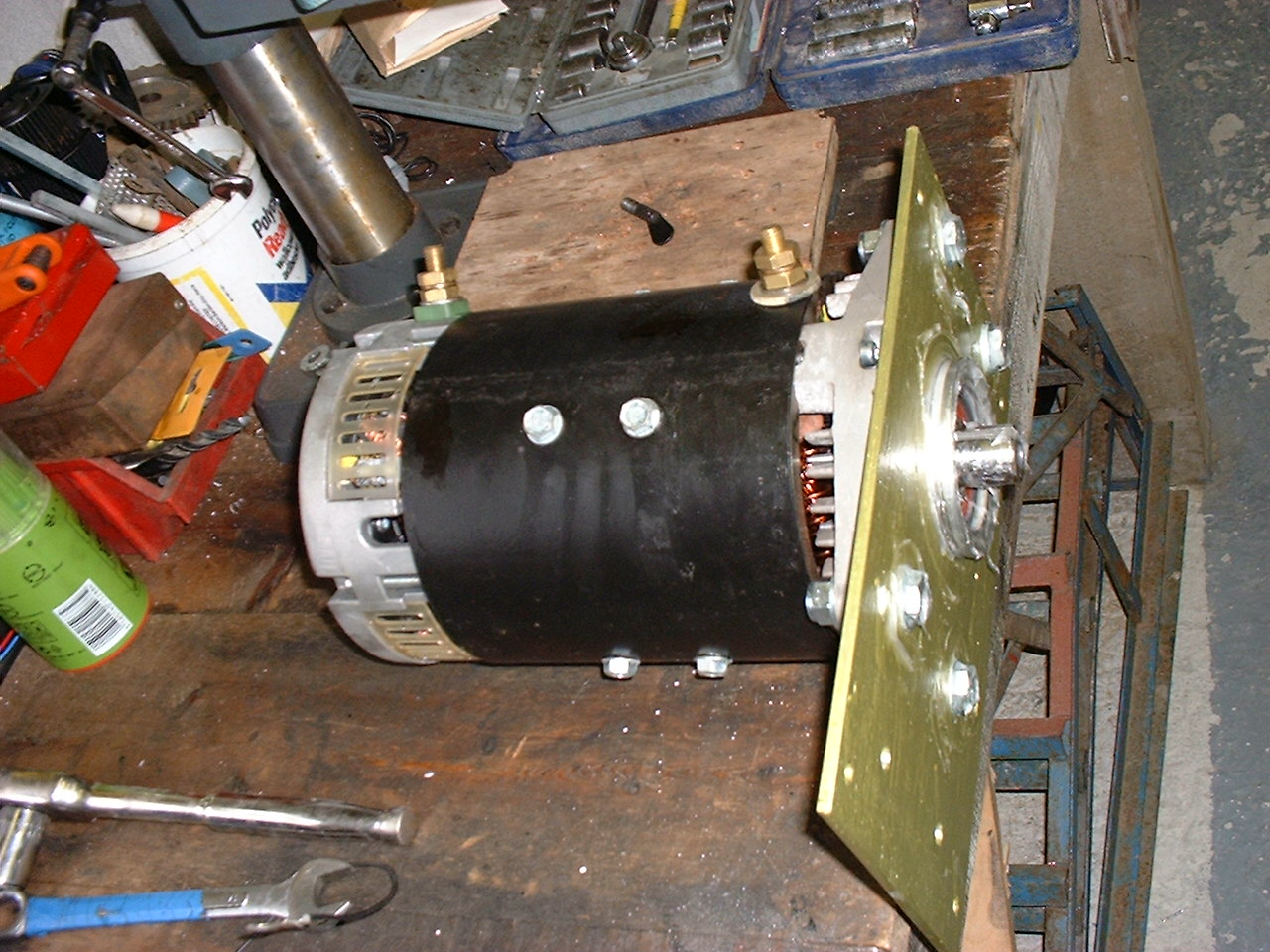
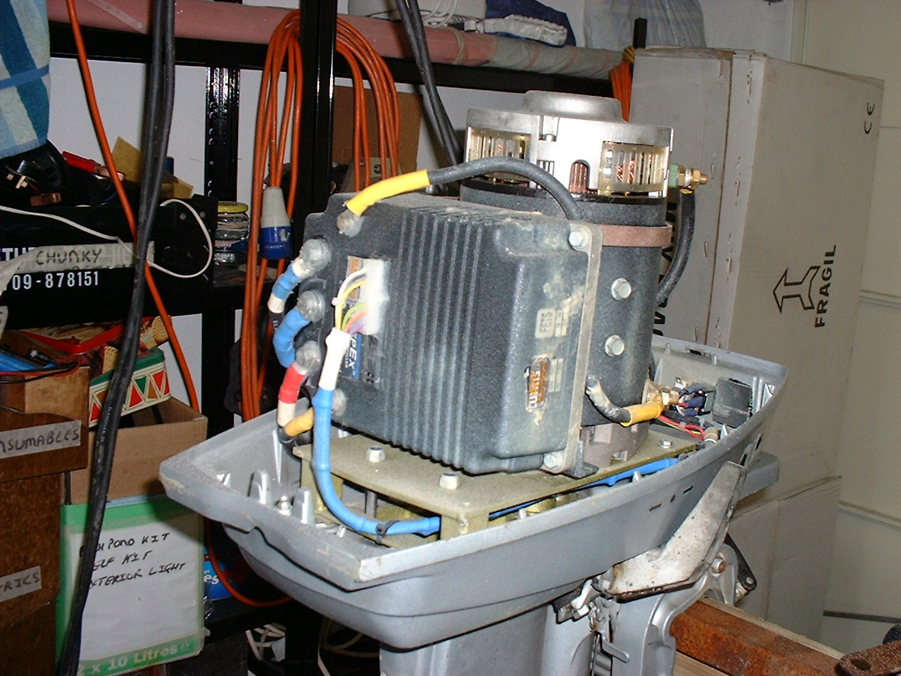
ADC Sepex 8Ē motor was found to be capable of producing up to 4000 rpm with 25 Hp available. The main down side is the motor mass, at 25 kg were highly likely to go over our unit mass budget. So we have a narrowed down our drive to the LAAA4002 using our requirement although we do have an alternate if we stretch, or get a concession, on our requirement. 4. Motor Coupling Not a great problem here as once the drive leg is stripped down we can modify the shaft coupling. The shaft is straight and the simplest form of link is to have a key ground on the shaft and then to manufacture a keyed coupling to match the motor at one end and the leg at the other. The electric drive will run smoothly but all the same we will use a double locking key in the instillation. It may be posable to buy a commercial off the shelf coupler however as we may want to have some compliance on the shaft length we will manufacture our own once the shaft alignment has been identified. Using the motor drawings it is posable, using the shaft detail, to draw up the motor to drive leg interface and it is here we define the coupling length and how we mount the motor. The motor is around the same mass as the original engine so we can use the original motor mount points although we will have to fabricate up a mount plate and stand-off to ensure the motor is square to the shaft and aligned. If you grab the shaft and give it a wobble its easy to realise that lateral alignment is not too critical however we should be aiming to minimise vibration and should therefor make all efforts to keep shafts aligned.
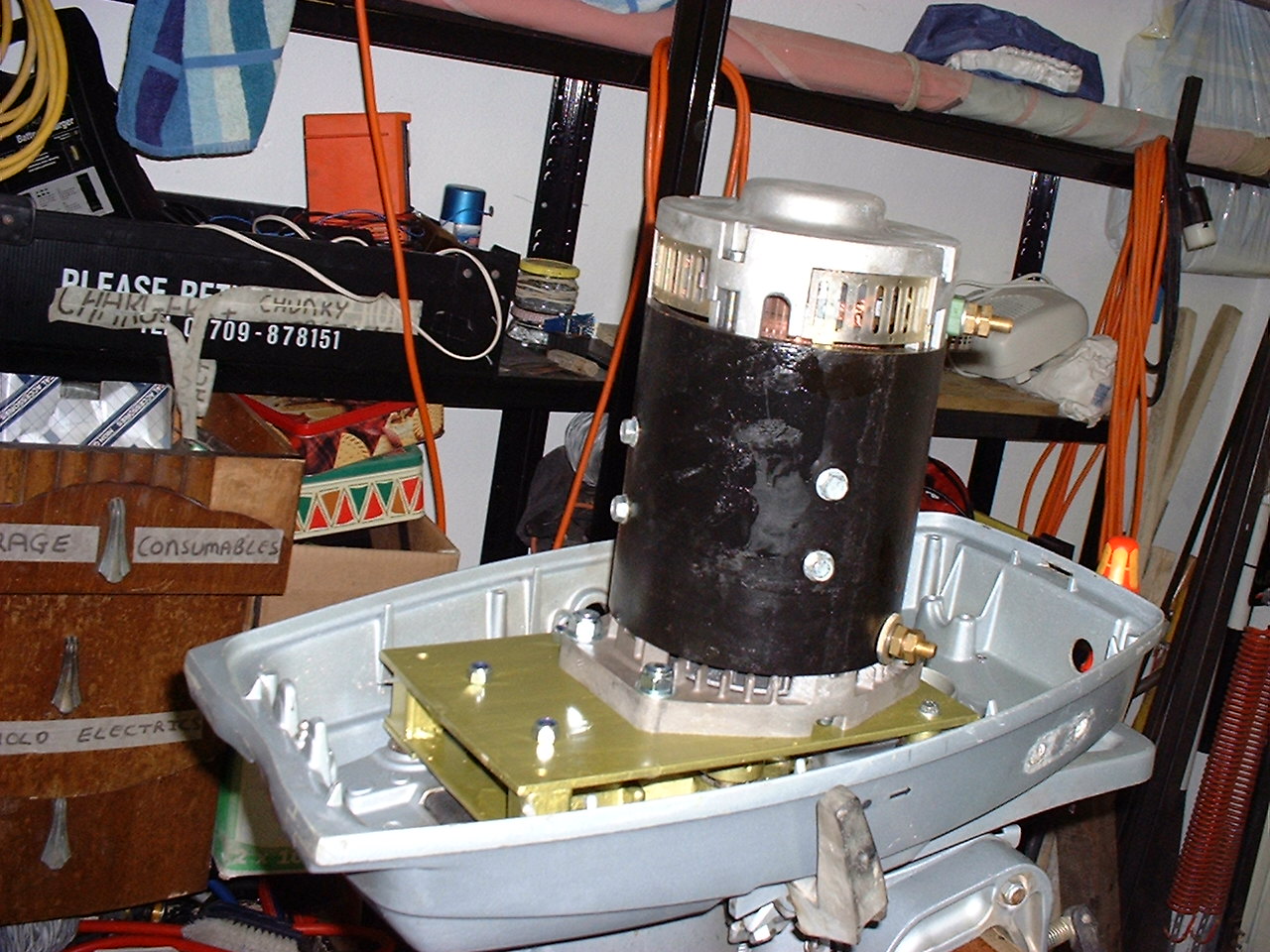
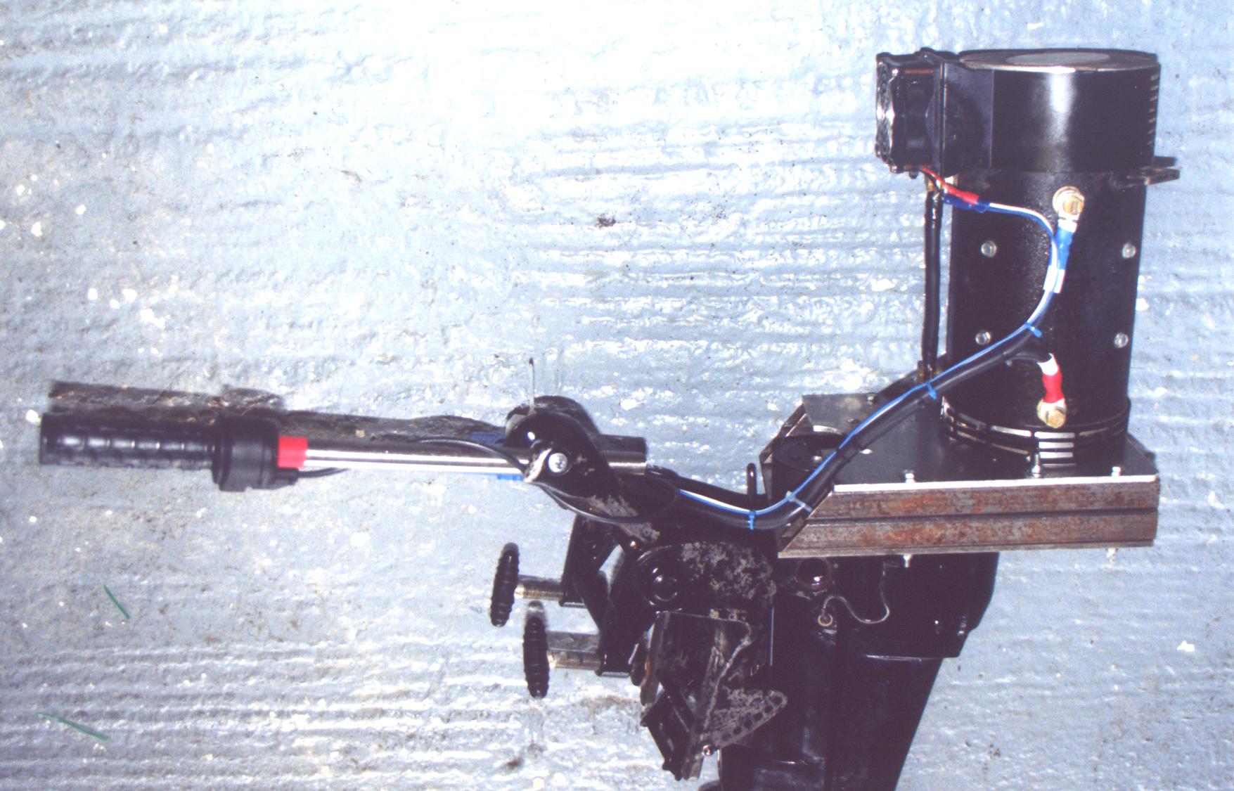
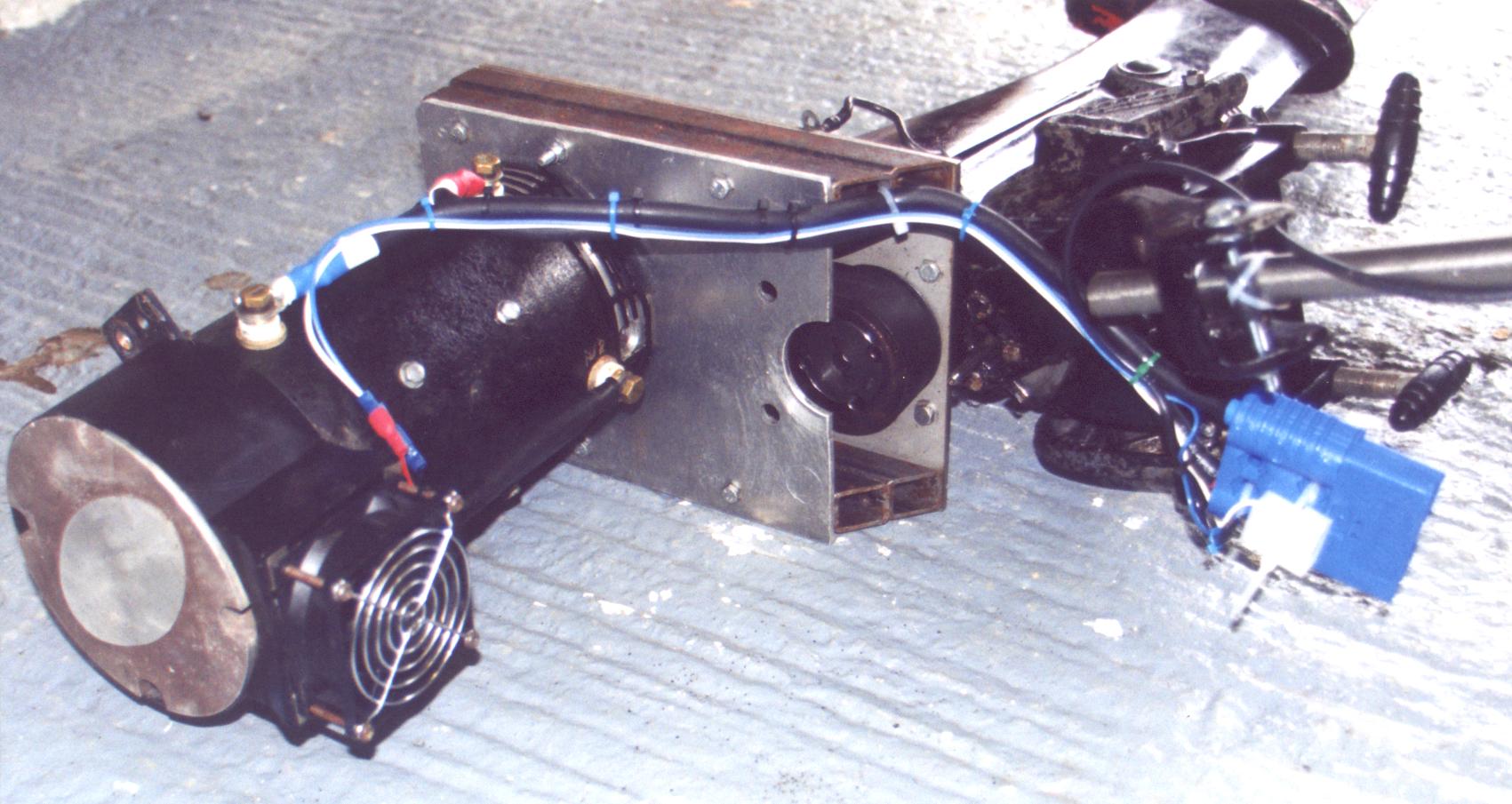
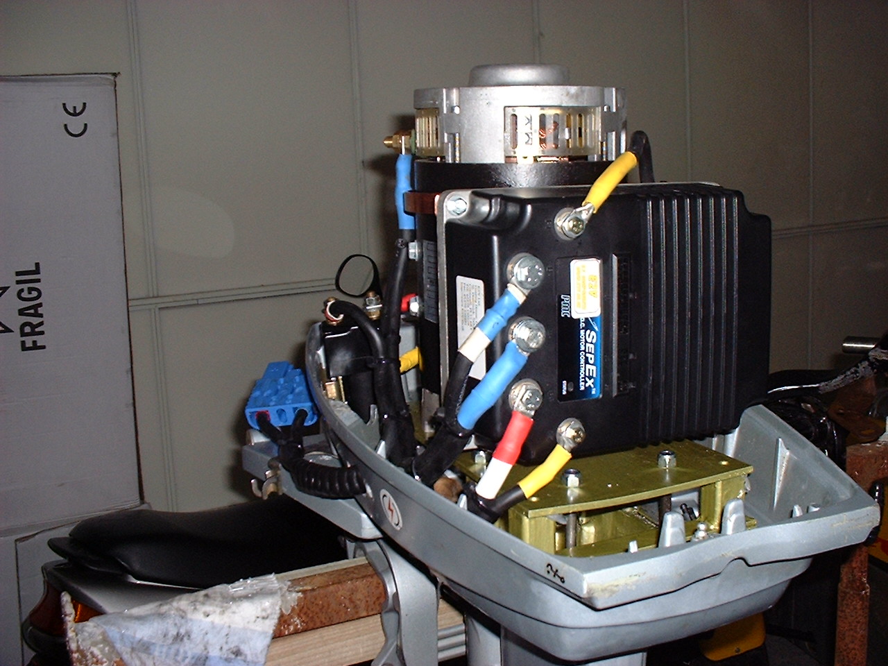
Shown here are the mount made for the Sepex motor on the 25 Hp leg. The plates and mounts were all scrounged up from parts lying around our lab but it can be seen that the coupling is very straight forward and that the motor in the leg does not look out of proportion thus obeying the fundamental design rule, if it look right etc etc.
The 10 Hp leg had a similar design although it was a little more rough and ready as we had another application for the motor. We also incorporated a belt coupling to increase the effective load on the motor as there were concerns on over speeding the motor.
5. Environmental A boat by its very nature resides in a highly humid environment, well water is about as humid as it gets! That said the motor is well clear of the water being up on the top of the leg so a basic cover should suffice in the protection department. To further aid corrosion resistance all electrical connectors will be coated with a protective layer and any switches and exposed metal will also receive the appropriate coating. In the case of the mounting plates they were painted with a heavy duty paint then the system was coated with Waxol to give a overall protective coating. The sepex motor runs very efficiently and as such very cool. We were able to maintain a good coating and to date the motor seems to be in good condition. Bolts and fixings will be and were stainless steel. The images show the motor controller mounted into the motor space and then the Waxol applied for protection. The Waxol is applied hot as a spray and penetrates the connectors and bolts. It is important to keep the brush gear clean and this was pre-masked to that end. 6. Modularity By using the original drive leg as a base for the drive module it is posable to have a easy to handle pre made unit that for the 10 Hp version contained the motor and user interface and for the 25 Hp version contained the motor, controller and switcher. It was decided that to ease use a remote was required and for the 25 Hp motor we manufactured a wired remote on, enable and speed control. The 10 Hp controller would be housed in a plastic enclosure capable of containing the relay, start switch and controller. A waterproof gland will allow power in to the unit and a second will output power to the drive. The control interface will have a socket mounted in the case. Batteries are probably the heaviest component in the build and to keep within our requirement limit it will be necessary to handle them individually. As such our battery box and terminationís must be such that it is easy to plug and play with our batteries. The batteries contain a lot of energy so it must not be posable to incorrectly connect them so battery leads and connectors must be polarised. This can be done by designing the battery box in such a way as looms can only be connected correctly and so that batteries only fit one way. 7. Operator use By meeting the targets of 6. we should now have a system where the operator can unassisted fit the motor, control box and batteries. Naturally it is unlikely that he would be alone however this is the time to add handles/straps where it may help. Remember that if the operator is loading from a pontoon the platform may be wobbly! 8. 30 kg unit limit This is tricky as we already have a motor that is 25 kg that is linked to a drive leg. Confession time, our 25 Hp drive was over weight, the outboard topped out at around 40 kg but in our defence it did make for a very neat package all be it a 2 man lift, or one strong one. Remember that lifting 40 kg is one thing, placing a 40 kg unit carefully aligned on to the back of a boat is another. Ours was a 2 man lift. We did hit target with the 10 Hp leg and this left the batteries to be the main mass unit. To get a handle on the battery pack mass we need to move on to requirement 10. but first we will contend with 9. 9. Working voltage In the UK we have a low voltage directive that when read between the lines steers us to having a low shock risk supply of less than 50 Volts. Ahh so we all say 48 volts is in huzza, but not so fast. A 12 volt battery, for we work in units of 6 or 12 Volts in the EV world, has a nominal voltage of 12 Volts. The key work here being nominal, the actual voltage of our 12 volt battery can range from 10.5 volts, low and under load, to 15 volts, final stage of charging, so we could have a battery pack potential of 60 Volts. As well as being a safety issue here we should consider our controller rated to 48 volts is now seeing 60 volts. Panic ye not, ok so we have potentially 60 volts in our battery pack but this will quickly decay to a more typical 52 ish volts. Wooly I know but thatís batteries for you! There is a huge range of battery volts that are dependant on state of charge, discharge rate, temperature, age of the battery and what mood your in. Ok that last one is me being a bit flippant but you get the picture. In general expect you fully charged battery to be around 13 volts a block, give or take .2 volts, and you should expect it to be able to hold 12 volts, when full, under normal load. Why 48 volts? Good question, we could go safe on the upper limit and go 36 volts but by doing so we move our upper battery current from around 200 Amps to 280 amps. Does it matter? Well every conductor we use has some resistance, as such they all loose power all be it not to much. That power however is related to the square of the current. And I hear you cry, well lets say the cumulative resistance of your battery leads is .05 ohms, at 200 amp you loose 2 kW in your battery leads, thatís 20 %! Now if we were running 36 volts that increases to over 3.8 kW nearly double the power loss. This is why in the road vehicles we tend to higher voltage. If we were running this system with the same resistance at 120 Volts our power loss would drop to around 350 watts, big difference but I would be nervous in this application having that voltage level hanging over the water. The other thing this does point out is use good cable and size accordingly. 0.05 ohms is still quite high but by the time you have all your terminals, connectors and battery internal resistance its likely to be realistic. We can easily achieve our working 48 volts using standard 6 or 12 volt mono blocks and it is a relatively standard voltage so we should have no problem sourcing our electrical system components. 10. Sizing the battery pack The drive will be capable of running for a minimum of 2 hours at 25% load. Ok os we are working to run at 2.5 kW for 2 hours. at 48 volts thatís a nudge over 50 amps, allow for a little loss in the system and lets budget for 55 amps. So we need a battery that will source 55 amps for 2 hours. Donít fall in to the that a 110 Ah battery please camp. Batteries are generally rated at their C20 rating, that is the equivalent energy the battery can produce over 20 hours rating. You need to ask for the C2 rating and do not be surprised to see a greatly reduced number, typically around 1/2 the C20. After that look at the cycle life and see how that battery will last if you discharge it to 100% every time. The answer in short if your chemistry is lead is very poorly and probably less than 100 cycles, ouch this is looking expensive. My 1st estimate and guide would be this;
So as a guide were looking for a battery pack with a C2 of around 220 Ah at 40 volts. This will give our pack some reasonable life and in the long run reduce the operating cost of our EV. Look carefully at the curves for cycle life and depth of discharge. You can quickly appreciate why opportunity charging is so very important to pack life. Ok for our application I have also decided to use a SVLA, sealed valve regulated lead acid, battery to reduce the risk of spills as we have indicated that there will be battery handling in the normal operation. I have also down selected to use a GNB 110 Ah unit as it just scrapes in under 30kg and by using 8 blocks in 2 string I can keep my block current down to a nominal 25 Amps, well within the requirement. On the down side though my battery pack mass has gone up to 230 kg, a significant jump. My options are to downsize or live with the weight. Back to Andy who decides the weight is not an issue and the decision is clinched by the fact that I already have some blocks in the garage, job done! Were lucky in this application that our displacement hull can accommodate the mass and volume easily and in general this is the case for displacement vessels. By building our battery box in to the bilge we also increase the stability but a note of caution here as batteries can gas and a bilge is very good at holding gasses. Our hull was open so we did no more than note the risk but you may want to fit a fan and extraction system. Also note that the batteries like to be run at around 22-24 degrees C sop if your operating in cold water, as we were, think about insulation or even heating for your battery bay. 11. Fuel Gauge Your battery pack is your energy store and how you treat your pack will define its life and ultimately the running cost of your vessel. A battery monitoring system will highlight problems early and will pay dividends in the long run. At its most basic you can buy a simple Curtis 10 segment bar graph type battery energy meter and I confess to using these regularly. There very cheep and Iíve found them to be very accurate as well as easy to use. They require only 3 wires so are even easy to fit. I would consider them to be the bare minimum. A battery volt meter is also a useful tool as an experienced operator will be able to identify trends and drive to the battery status. A current meter is also useful and in a water craft with a non sprung throttle it is often desirable to set a drive current to maximise the battery life. The obvious step is to have a single unit that does it all and there is such a unit.
The Link 10 has a basic LED segment fuel gauge but can display pack volts, current state of charge in % and remaining Ah. The unit is programmed to match your pack and is about as good as they get short of metering block by block. Metering block by block, ok this is the ultimate and if the project is a bespoke and built EV then it may be worth considering. It will require much additional wiring and is beyond the scope of this guide but in a larger system with a sizeable and fixed battery pack it would be prudent. 12. Have Fun Now this comes down to your definition of fun but its always a good idea to get a team of friends on board to help. Everyone will have some opportunity for input even if its just deciding the colour of the vessel! Donít forget to get your partner involved as there will be a time when a morale officer is as important as the 1st mate. At the end of each day write up a log and take plenty of pictures. Start the day with a to do list and youíll have a better feeling of achievement come the days end. Donít take chances, if your not sure ask an expert, its easy in this game to break something expensive and its always best to ask before breaking. Keep a tidy workshop and assign a place for storing the Ďcleaní systems. Above all enjoy the project. Good Luck Dave
|
|
[Home] [Contact Us] [Gallery] [Tech Stuff] [Electric Outboard] [Sparrow #10] [Think!] [Links] [RDYC] [Wedding Private] |
